


Nos marchés
Le groupe Defontaine, avec ses deux marques, a su s’imposer depuis plus de 70 ans chez plus de 1300 clients sur 5 continents, là où les concepts de qualité, fiabilité, durée de vie et coût d’utilisation sont la priorité.


VisionCreating sustainable value
Le groupe Defontaine, en créant une relation de partenariat avec ses clients, s’inscrit dans la durée. Cette vision d’accompagnement de proximité de nos partenaires est basée sur 3 piliers.
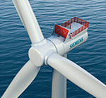
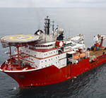
Le groupe Defontaine conçoit et fabrique des produits vertueux recyclables à plus de 99% pour vos applications de demain en vue d’un avenir meilleur pour notre planète et les humains qui y vivent. Nos processus de fabrication particulièrement faibles en empreinte carbone vous accompagnent dans votre volonté d’améliorer votre empreinte carbone. Notre position de leader dans les énergies renouvelables et notre investissement pour rendre les moyens de locomotion de demain plus propres sont la preuve de notre engagement dans ce domaine depuis plus de 30 ans.
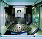
Le groupe Defontaine s’investit pour développer l’Usine du Futur avec des technologies automatisées et connectées pour améliorer la qualité de ses produits et en réduire le coût de fabrication. L’objectif du groupe est de placer l’intelligence artificielle au cœur de la production de demain. Le groupe Defontaine travaille ainsi à concevoir des pièces et sous-ensembles mécaniques instrumentés pour diminuer leur coût d’utilisation par une meilleure prédiction de leur durée de vie.
Les 1300 employés du groupe Defontaine ont la même volonté « chevillée au corps » : le service apporté aux clients. Ils et elles travaillent ensemble dans un même esprit d’amélioration continue avec une exigence sans faille, la bienveillance envers les autres et la sécurité de tous.
Nos services
Defontaine est un groupe international où la proximité avec ses clients dans le monde entier est une réalité quotidienne.
Depuis la conception du produit jusqu’au service après-vente, en passant par la fabrication, la logistique, le conseil lors du montage dans vos ateliers et les pièces détachées en stock, les hommes et les femmes du groupe Defontaine vous accompagnent. Notre volonté : que notre partenariat soit une réussite de chaque jour pour promouvoir l’excellence de vos produits sur le marché mondial.
 Roulé-soudé par étincelage
 Usinage et rectification de précision
 Trempe sous presse
 Traitement thermique par induction
 Procédés spéciaux
Ils nous font confiance


Nos dernières actualités
Pour ne rien manquer du groupe Defontaine, suivez toutes nos actualités : coulisses de l'entreprise, recrutements en cours, réalisations, événements, ...

